

Description
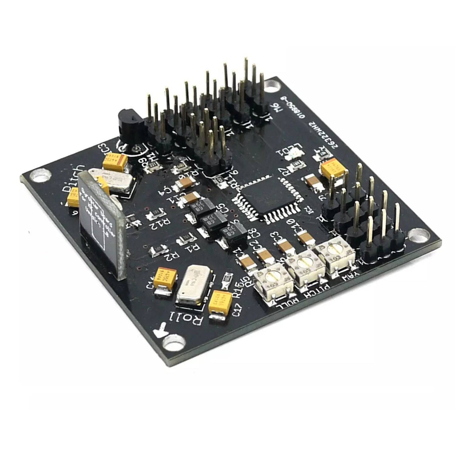
The KK Multicopter Flight Control Board V5.5 is a versatile flight stabilization controller designed for remote-control multicopters with 2, 3, 4, and 6 rotor configurations. Using onboard gyros and an integrated Atmega168 microcontroller, the board continuously processes aircraft orientation data and adjusts motor speed via Electronic Speed Controllers (ESCs) to maintain stable flight.
The controller receives pilot commands from the RC receiver and dynamically controls motor output for movement including pitch, roll, throttle, and yaw control. In tricopter configurations, a dedicated servo output provides yaw control capability.
The V5.5 version includes an onboard ISP header, allowing developers and enthusiasts to modify and upload custom firmware. It supports multiple flight configurations, making it ideal for hobbyists, RC builders, and educational drone projects.
Features:
- Supports 2, 3, 4 and 6 rotor multicopters
- Integrated Atmega168 microcontroller
- Three-axis gyro stabilization system
- Compatible with tricopter, quadcopter and hexacopter builds
- Dedicated tricopter servo output
- Custom firmware upload support through ISP header
- Real-time stabilization and flight correction
- Supports multiple rotor configuration firmware options
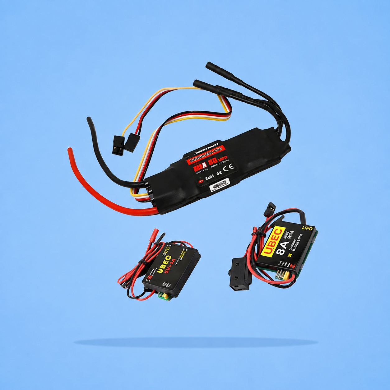
- Compatible with Electronic Speed Controllers (ESCs)
- Uses Murata piezo gyros with improved vibration resistance
- Lightweight and easy integration design
Flight Configurations Supported:
- KKOsprey (2 Rotor)
- KKTricopter (3 Rotor + Servo)
- KKQuadrocopter (4 Rotor + Configuration)
- KKXcopter (4 Rotor X Configuration)
- KKSexycopter (6 Rotor)
- KKYcopter (6 Rotor Y Configuration)
Package Includes:
- 1 × KK Multicopter Flight Control Board V5.5
Mounting the KKmulticontroller in your multi-copter:
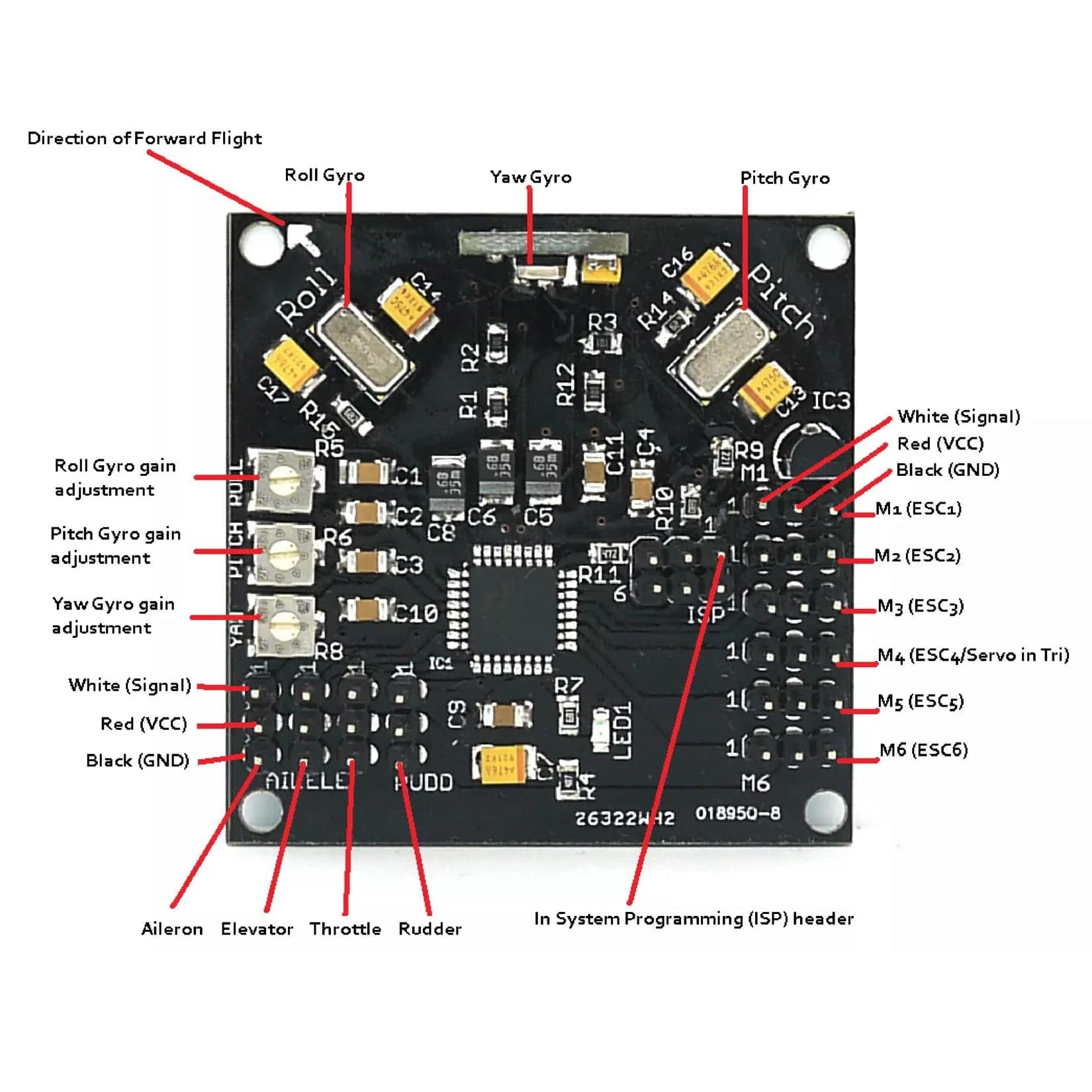
The v.5.5 KKmutlicontroller uses Murata piezo gyros that are less sensitive to vibration than SMD-type gyros, but it is still a good idea to mount the board on a vibration-dampening material. The board must also be mounted with the white arrow facing the direction of forward flight.
When connecting your Remote Control Receiver (RX) you must connect the white signal wire of the channels (CHI, CH2, CH3 and CH4) from your RX corresponding to the aileron, elevator, throttle and rudder to the inner pins on the board while the red (VCC) wires are connected to the centre pins and the black (GND) wires are connected to the pins on the outer edge of your board.
The pins marked MI to M6 are connected to the 3-pin BEC plug from your ESCs. They follow the same convention as the RX pins with the white wires connected to the inner pins, the red wires to the center pins and the black wires to the outer pins. The ESCs and the connected motors are plugged into the pins M1 to M6 in the following order depending on flight rotor configuration. Note also the direction of rotation for each motor. This is achieved by connecting the three ESC wires to the motors and swapping two of the wires to achieve rotation in the opposite direction.

Reviews
There are no reviews yet.